Assembly
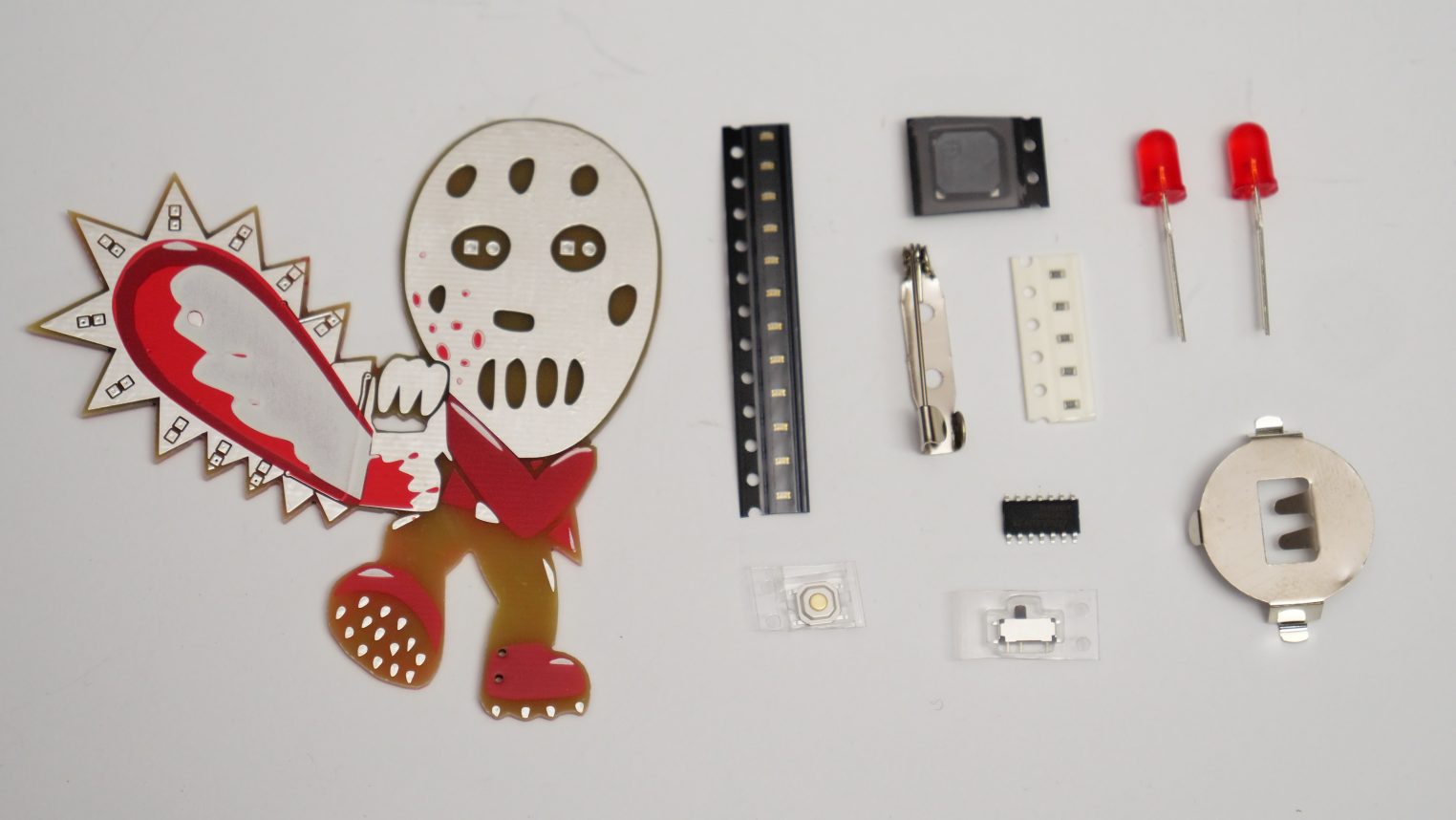
The badge comes as a kit that needs to be soldered to the printed circuit board. The micro controller is pre-programmed with a sketch animating the LEDs and playing sounds. The CR2032 is not included due to shipping restrictions but are commonly available.
The best way to start with the micro controller. The round points on the chip and the PCB indicate the right orientation.
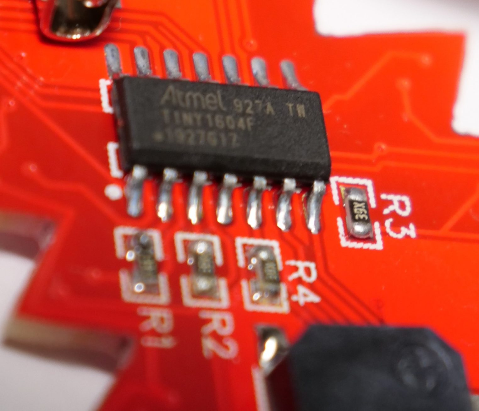
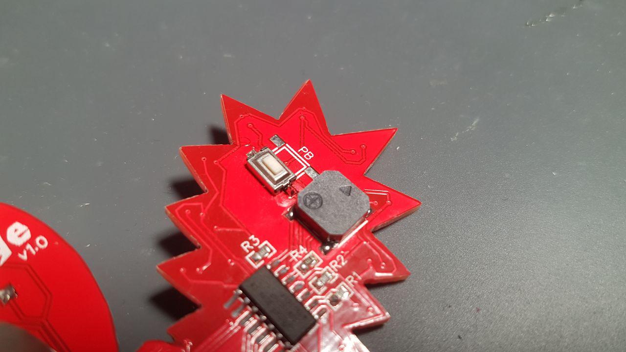
Next are the resistors, switch, the button and the buzzer. Solder flux helps a lot to control the solder. Since the buzzer is the biggest part consider soldering it last. The button has to be soldered on like this:
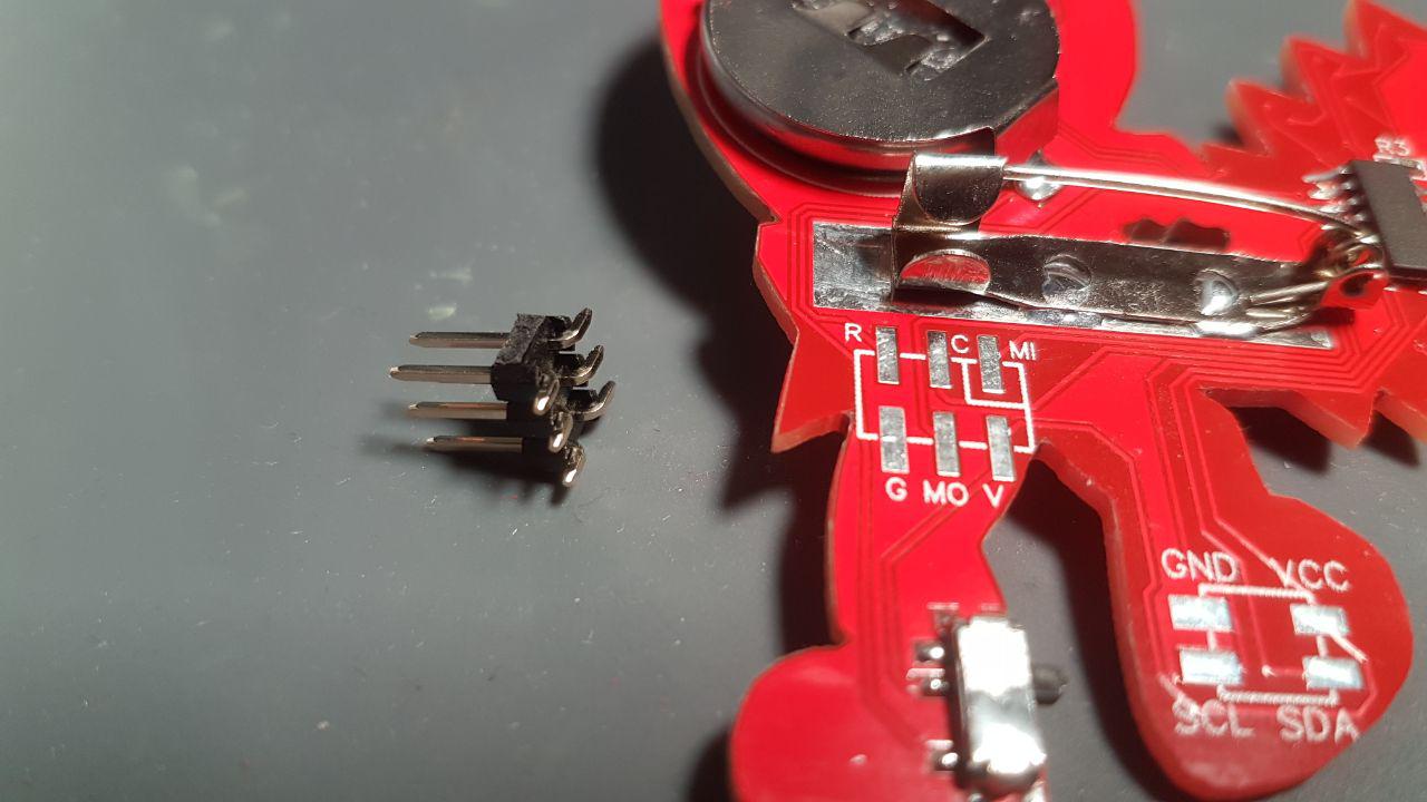
The 6pin connector is optional for developers. Don’t solder it on if you want to carry the badge.
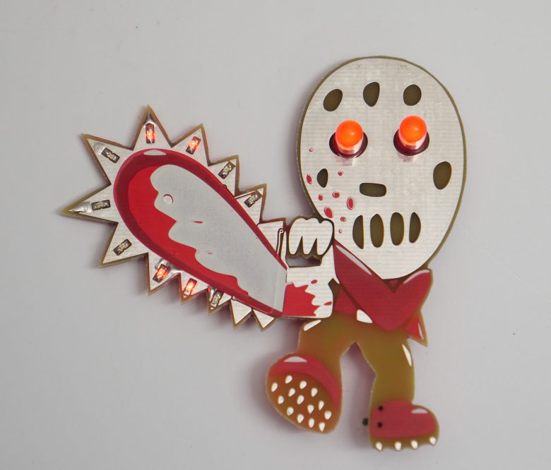
The 5mm trough hole LEDs are the eyes of the killer. The long leg of the LED needs to go in the quadratic hole on the front.
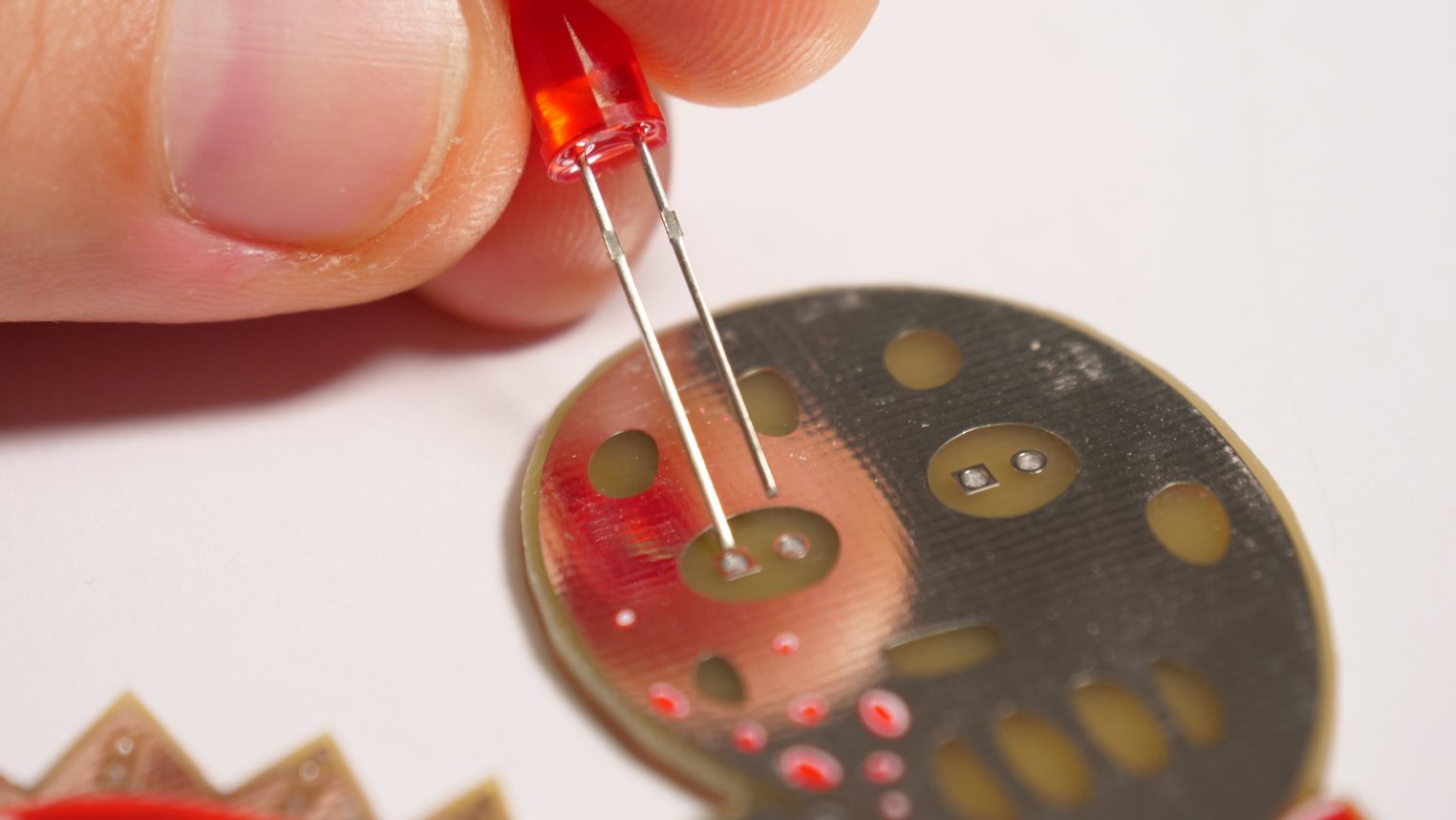
After the soldering of the LEDs the excess of the legs needs to be clipped.
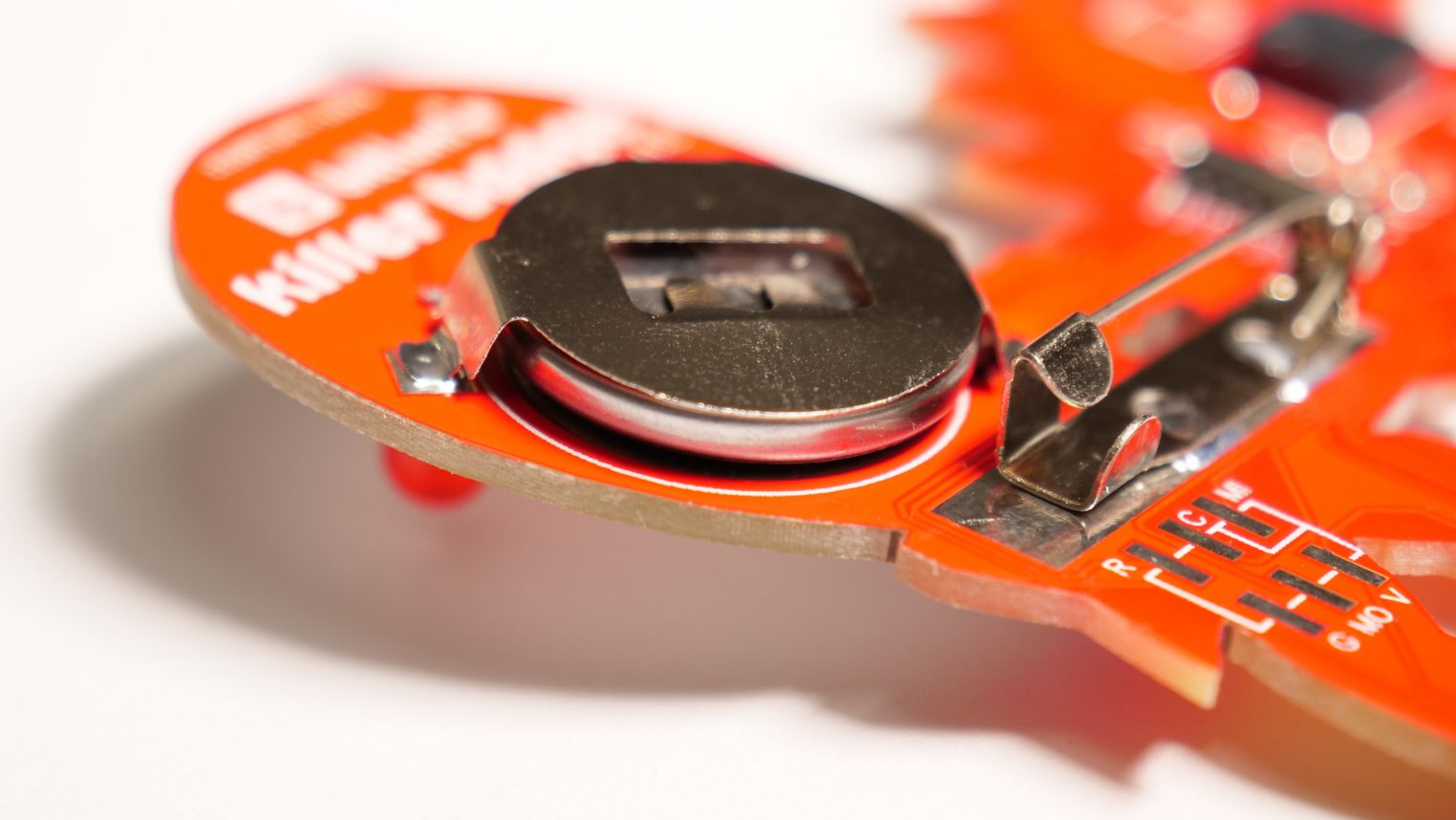
The battery holder can be soldered two ways. If the opening for the CR2032 is to the lower right the clip has to be soldered on the most right of the pad for the battery to fit. The opening to the upper right only the pins of the LEDs might annoy a bit.
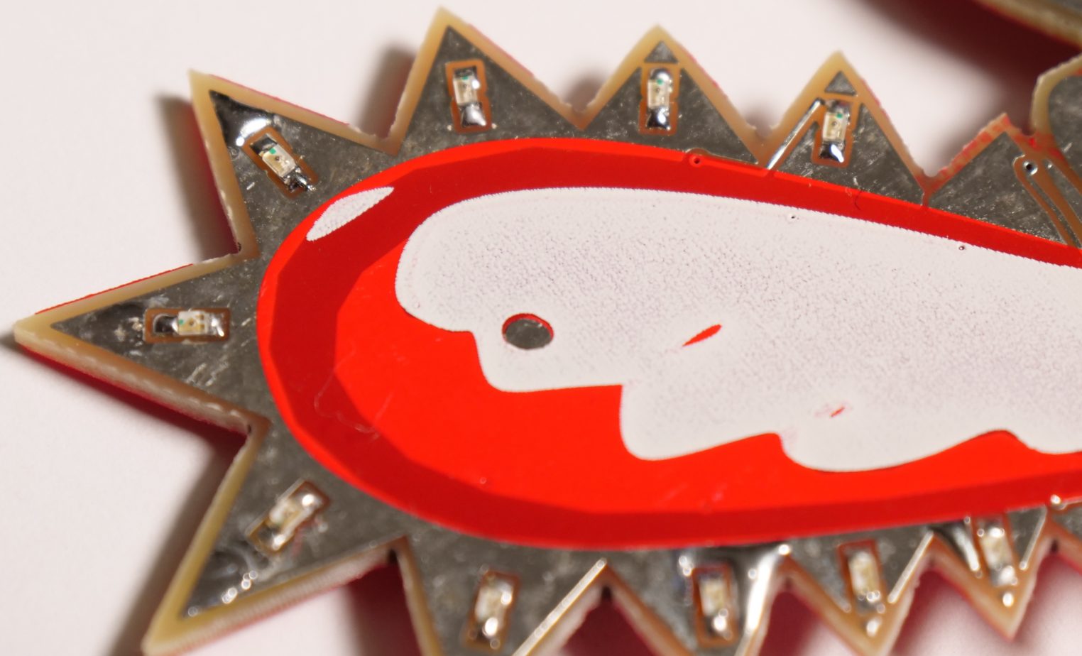
On the front side the SMD LEDs need to be soldered with a specific orientation. On the bottom side of the LEDs are T like markings. These should always point to the outer boarder of the PCB.
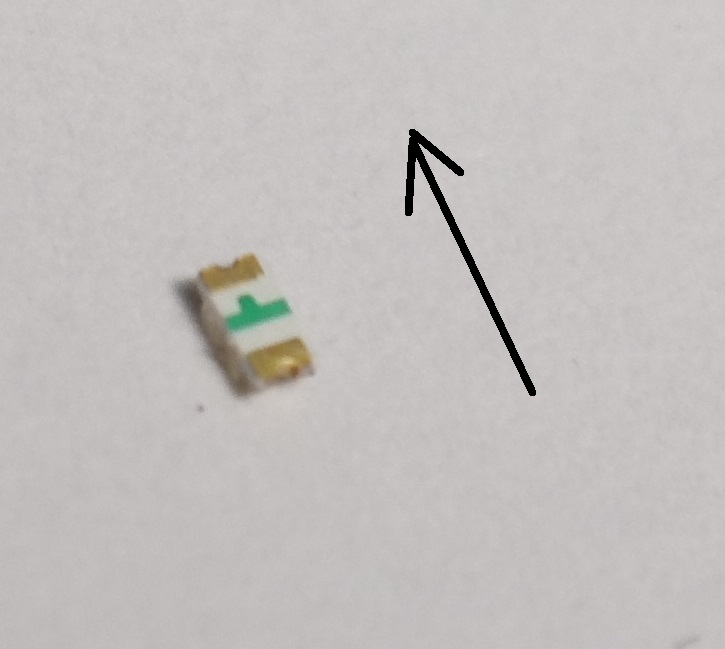
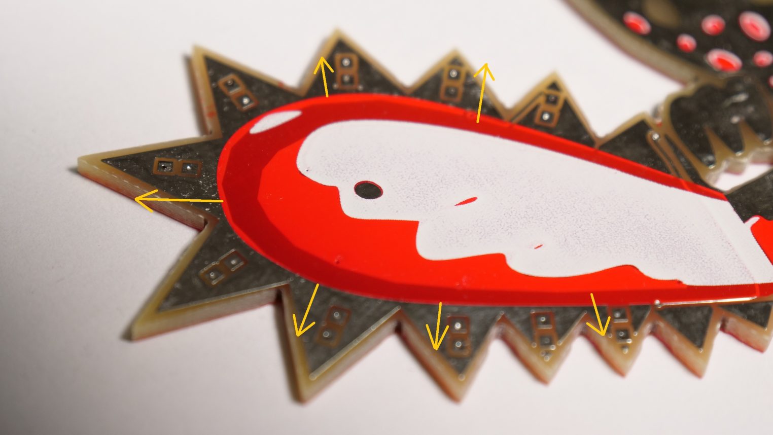
This is how the LEDs should more or less look like 😀
Done!
The switch at the leg turns on the power. The button on the back cycles trough the modes. A 2 second press plays a sample.

Programming the device
The Firmware is available here
When a battery is present only the R (Reset) and the G (Ground) have to be connected to the programmer.
!!!Warning if you want to use the external power source the badge switch has to be always on. Otherwise the switch will short your external Vcc. The circuit will be updated on that matter for future versions.
3.3V for Vcc is fine, 5V will destroy the LEDs if an LED is lit permanently.