VGA Board v0.1
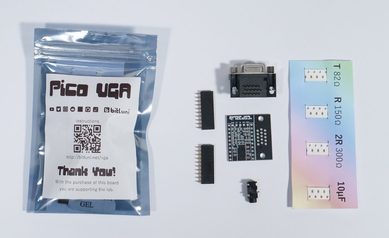
VGA Black Edition
The kit version of the Black Edition comes with the board, the VGA connector, three resistor values and two pin headers. The VGA connector might be put to the board to protect the pins from bending but it’s not soldered yet. The resistors are labeled with T (82Ohm), R (10Ohm) and 2R (300Ohm). The board is labeled to where to put the individual resistors. There are some spare resistors in case of some problems.
The assembly is similar to the VGA Board v0.1

The resistor footprints are quite tight. The resistors fit best at an angle by letting stick out one leg a bit longer. The longer leg can be used to tag the resistor with some solder before turning the board and soldering it properly.
After the soldering the board should be looking like this:

The mini kit has to be soldered with female connectors and placed on the board like this:

The antenna should stick out like this. This should allow a good WiFi reception:

PicoVGA
The Pico VGA ships either as a kit with all individual SMD parts
or as a partly assembled kit

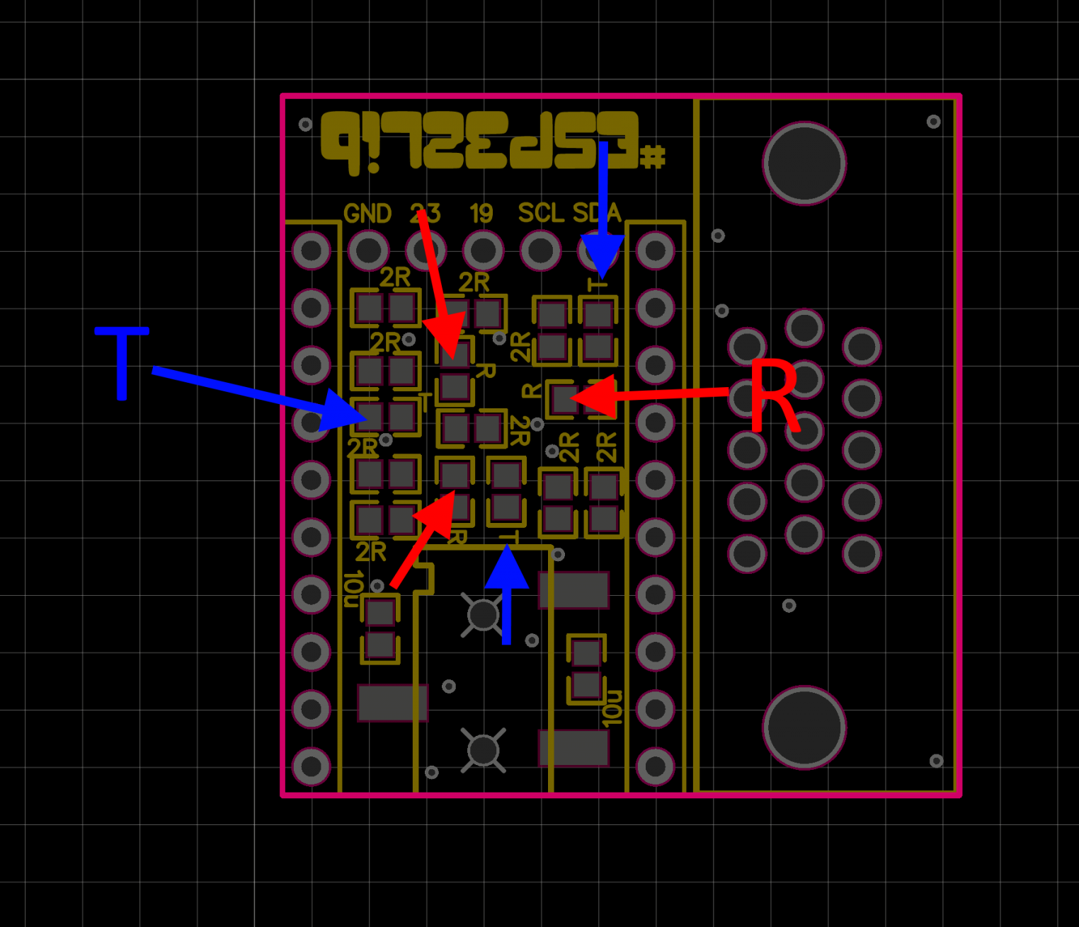
The SMD kit comes with spare parts. SInce the silkscreen might be a bit confusing here is pointed out where the T (82Ohm) resistors have to be placed in blue. The red arrows point where the R (150Ohm) resistors need to be placed. The two spots left and right to the audio connector are for the two 10µF capacitors and the rest are the 9 2R (300Ohm) resistors.
After soldering all parts it should look like this:

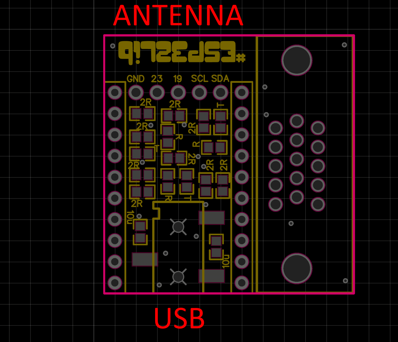
The USB connector of the TinyPICO has to be over the line out jack and the antenna covers the free space with the label #ESP32Lib when plugged in.
With the TinyPICO connected it looks like that. The audio connector won’t be able to drive headphones but will work fine als line out.

Software
To start developing you’ll need a development environment. The Arduino IDE is a good starting point.
The link you need to add for the ESP32 support to “Additional Boards Manager URLs” in the preferences after installation is:
https://dl.espressif.com/dl/package_esp32_index.json
You can find further info on the ESP32 support für Arduino in the github repository.
To get a starting point with your development I prepared the library “esp32Lib” that can be installed form the Library Manager. The examples provided with the library can be found in the examples menu under Custom Libraries after you selected the ESP32 board (MH ET LIVE ESP32MiniKIT) in the tools.
There are different pin configurations for different boards. The generic configuration can be done either as parameters of the init method like done in the most examples or using a configuration stored in the library like done in the latest examples Raytracer and 6BitMode.
vga.init(vga.MODE320x200, vga.VGABlackEdition);The available configurations are:
- VGAv01
- VGABlackEdition
- PicoVGA
- VGAWhiteEdition
VGAv01 and VGABlackEdition are sharing the same pin configuration. So all the examples using the discrete pin configurations will work out of the box. The 6BitMode example is pre-configured to PicoVGA since this one only supports up-to color 6Bits. The 14Bit modes will still work with the PicoVGA by using:
vga.init(vga.MODE320x200, vga.PicoVGA);The color resolution will be lower, though.
You are not limited to ESP32Lib (more info on github). FabGL is supported as well. However you have to configure the pins in the sketches yourself.