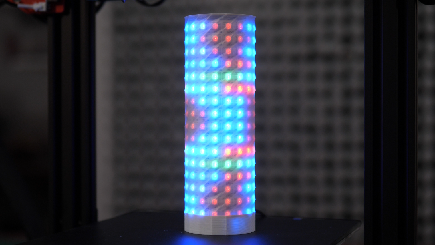
This tutorial shows the build of the mini lamp from the video in detail
Needed components (affiliate links):
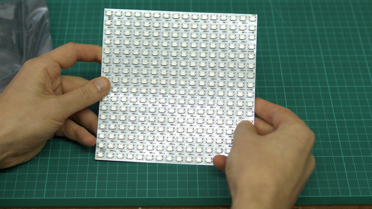
16×16 Flexible RGB LED Matrix ($13)
ESP8266 D1 Mini
Power Supply
5.5mm Barrel Jack
3D Print
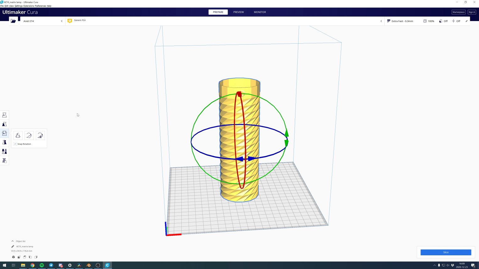
The blender and stl file can be found on thingiverse . The blender file is only needed if you like to modify it. The STL can be simply dropped in Cura which I used to slice the model for printing. The rotate tool can be used to flip the model up side down. This way no supports are needed and the model prints in under 4h with 0.3mm layerheight.
During printing the material can be switched between an opaque and transparent one. I have used opaque White and natural PLA which is translucent. First switch to a translucent material happens after a few layers when the cap is finished. Then again after around 161mm when the patterned region is done.
I have used the ANet ET4 printer (affiliate link) which supports pause and material switching during a print.
The lamp can be print from only one material. Some more diffusion or brightness loss might be the result but is even simpler to do.
While the long sections of the model are printed the simple soldering and firmware uploading can be done.
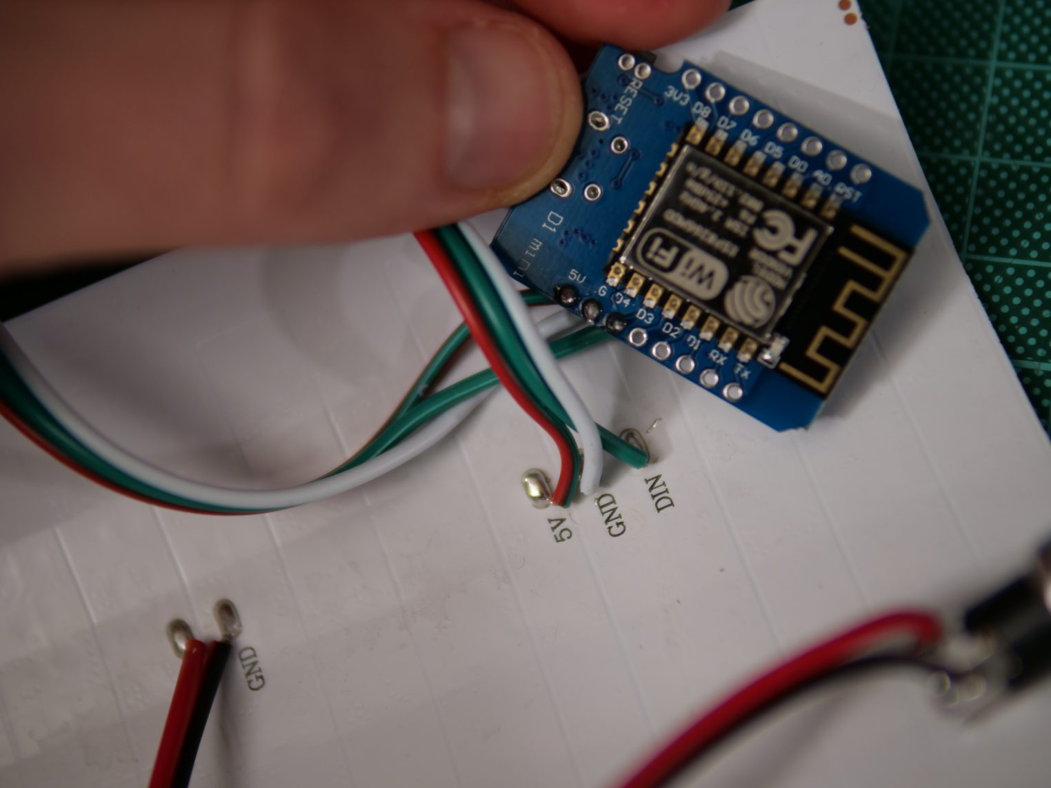
The LED-Matrix comes with an extra connector and three cables attached to the backside.
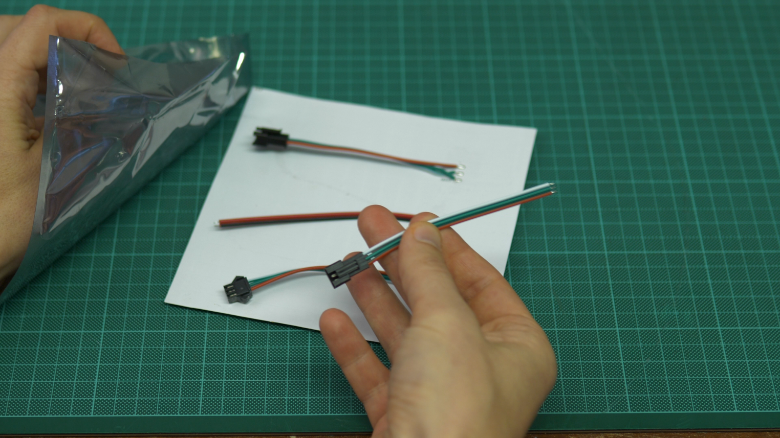
The barrel jack plug is soldered to the wires in the middle.
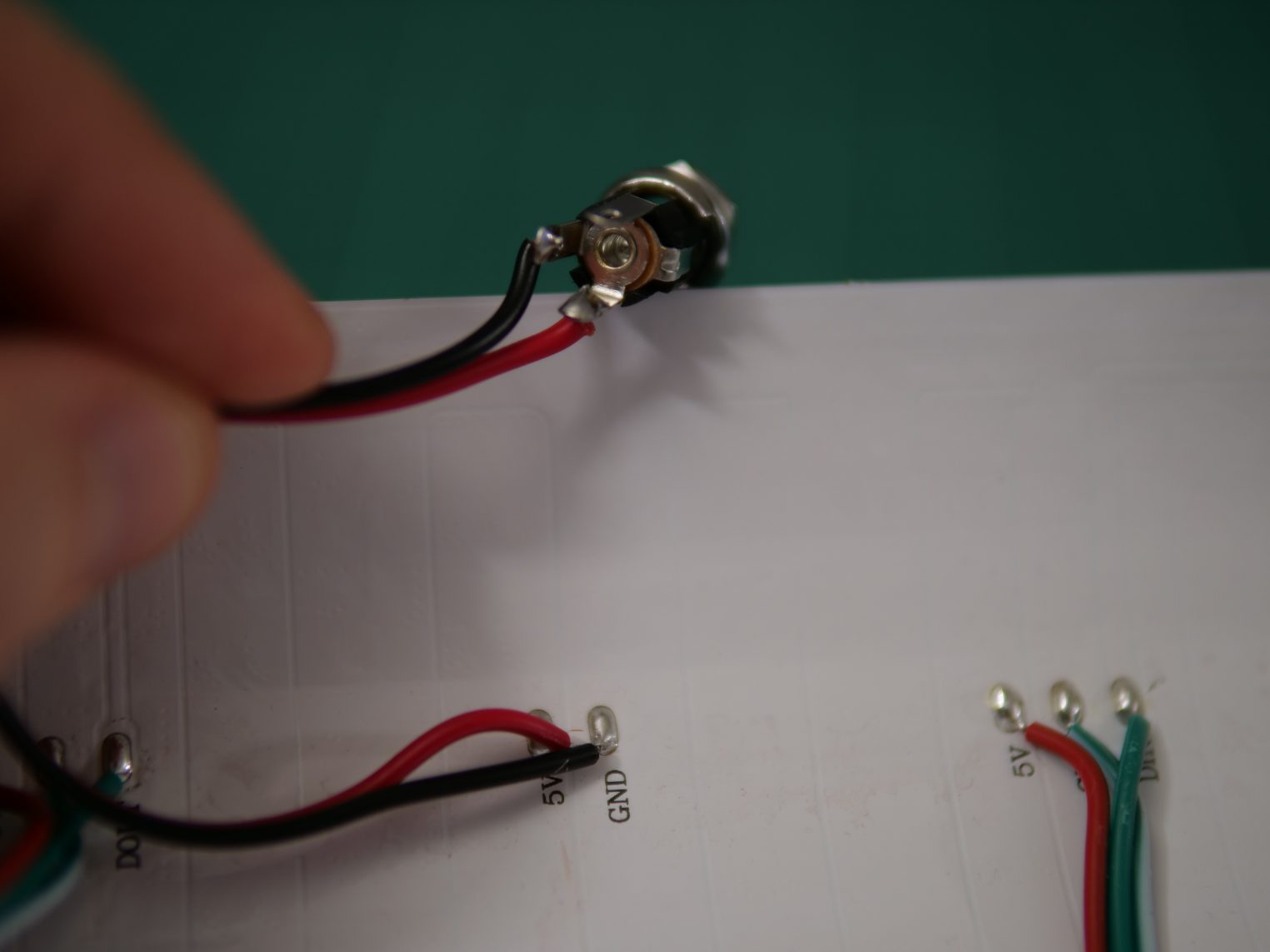
5V (red) are soldered to the center pin of the barrel jack. GND (black) to one of the outer pins. Please check the details on the power supply and measure the voltage using a multi meter at the jack pins before soldering.
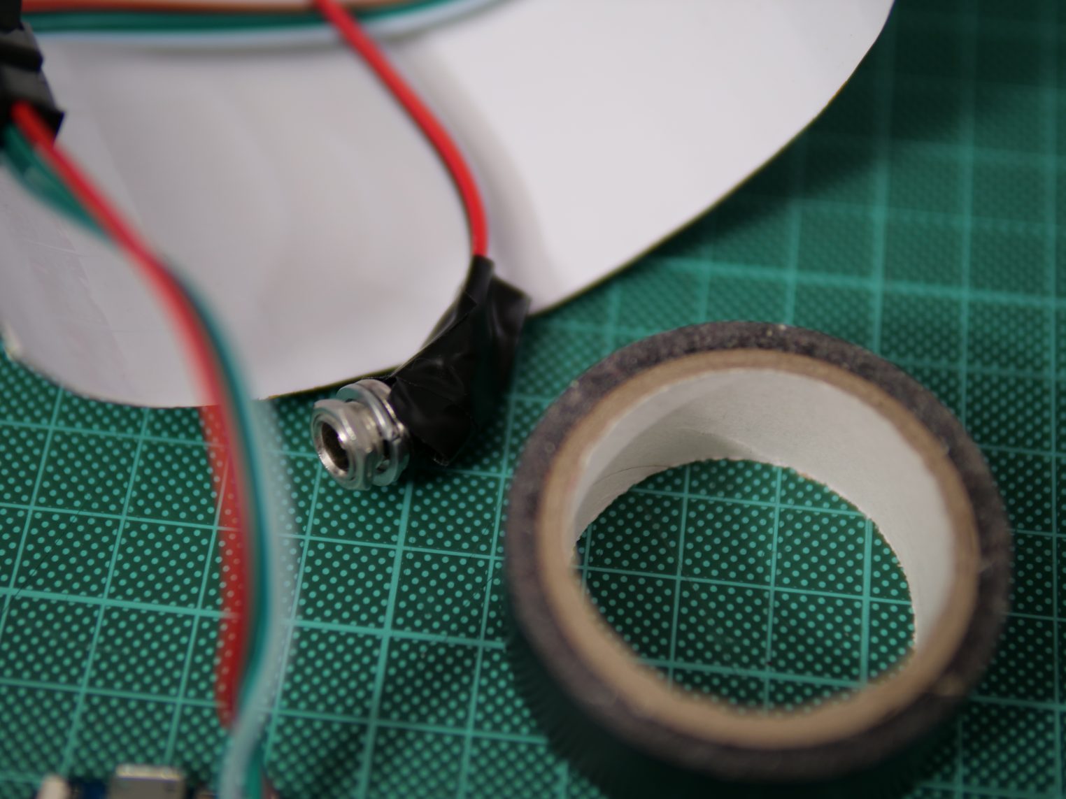
Some electrical tape helps to protect the exposed power pads from shorting later with the micro controller inside the lamp.
As the next step solder the extra connector to the D1 Mini. Red to the 5V pin, White to G and green to D4.
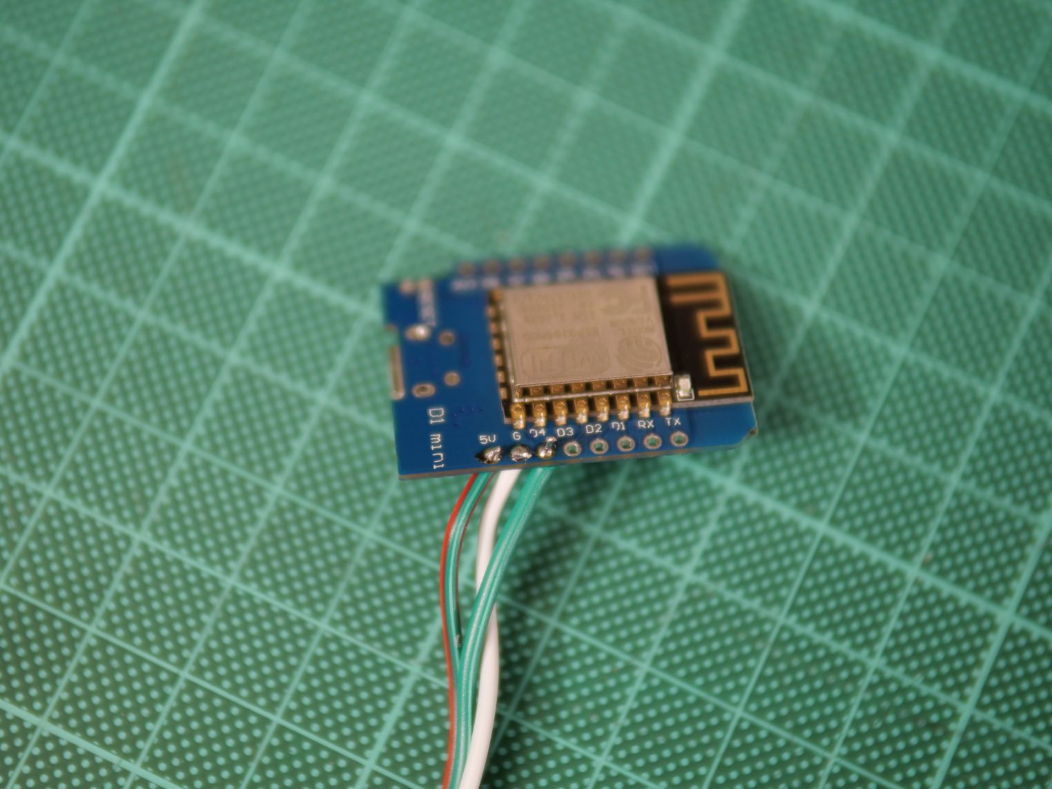
If there is different coloring on your connector check the labels on the backside of the matrix and trace which wire would be connected to which label. DIN means data in and should be connected to the data out of the micro controller. this is Pin d$ by default.
Before connecting it to the power or the matrix the WLED firmware needs to be uploaded to the micro controller.
WELD is open source and can be found here. However, there is no need to compile the project as binaries are available. This tutorial explains how to upload using the home flasher tool.
Shortly explained:
1. Download the ESP8266 binary from here i.e WLED_0.9.1_ESP8266.bin
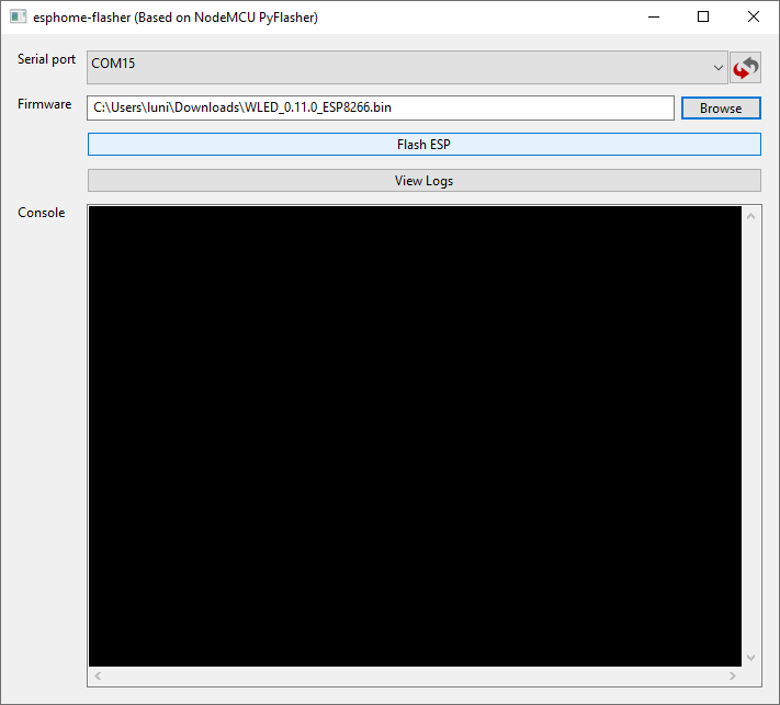
2. Download and start the ESP Home Flasher tool from here
3. Select the serial port that shows up after connecting the micro controller to the computer over USB and refreshing the first field.
4. Select the bin file in the second field
5. Click Flash ESP
The Console should show some output like in the video linked above. The flashing can take some time.
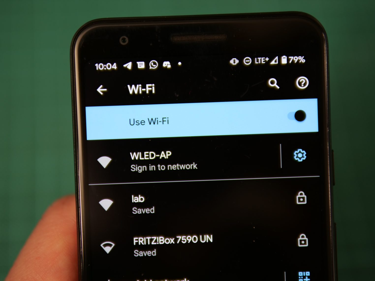
After the flashing is done WLED will open an access point which can be used to configure the device. By connecting to it it should open the configuration in the browser automatically.
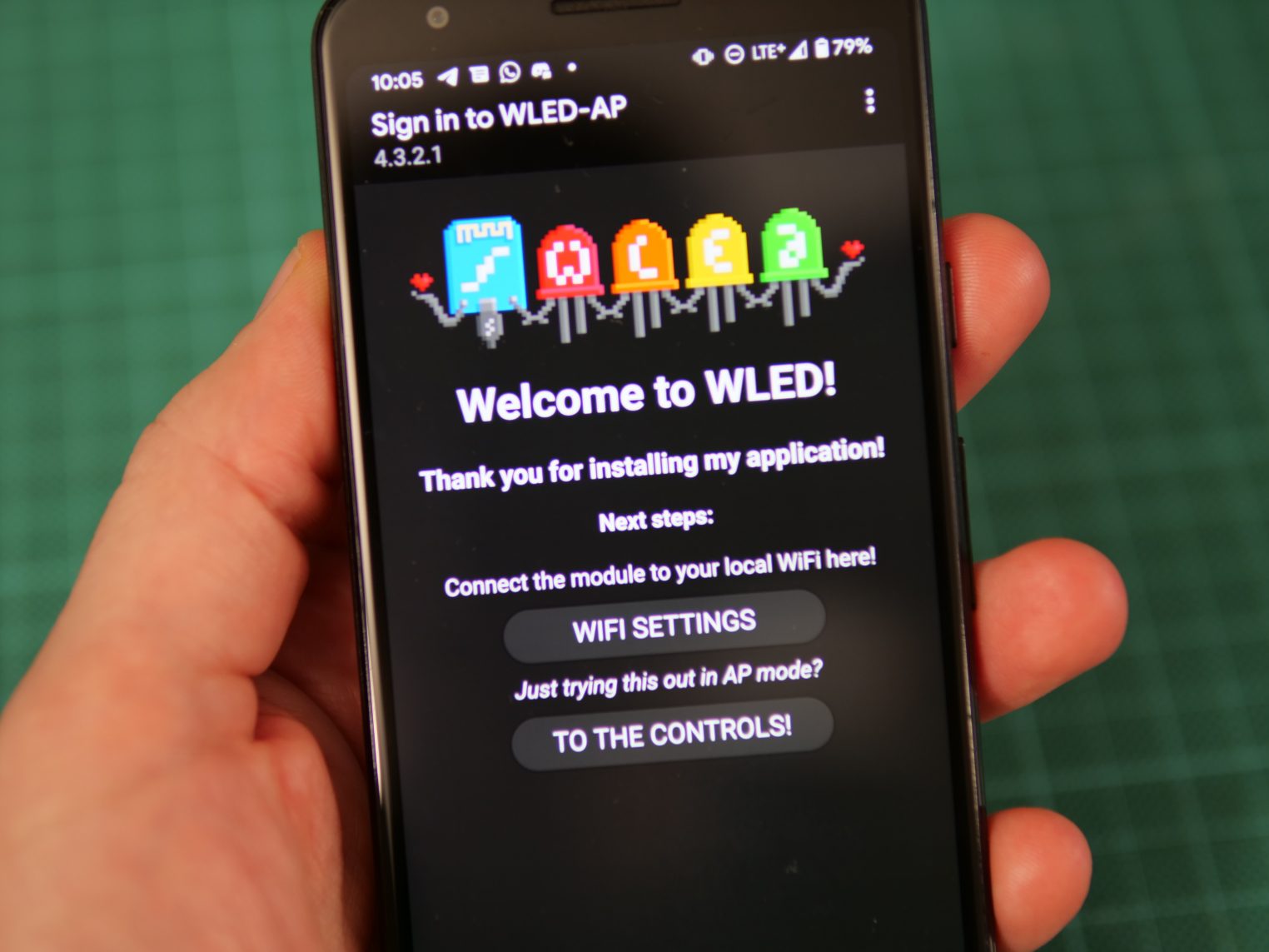
The device can be configured to login your home WiFi for an easy access from the WLED App. More on that can be found here.
To just get it started we only need to set the LED count to 256 and limit the current to 2000mA in my case.
Check your power supply for the maximum limit and consider a safety margin. The current limit results in a dimmer matrix when many pixels are lit.
The LED Preferences can be found following the buttons “To The Controls!” -> Config -> “LED Preferences”
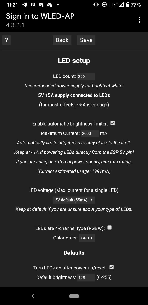
Don’t forget to save the changes at the bottom of the site.
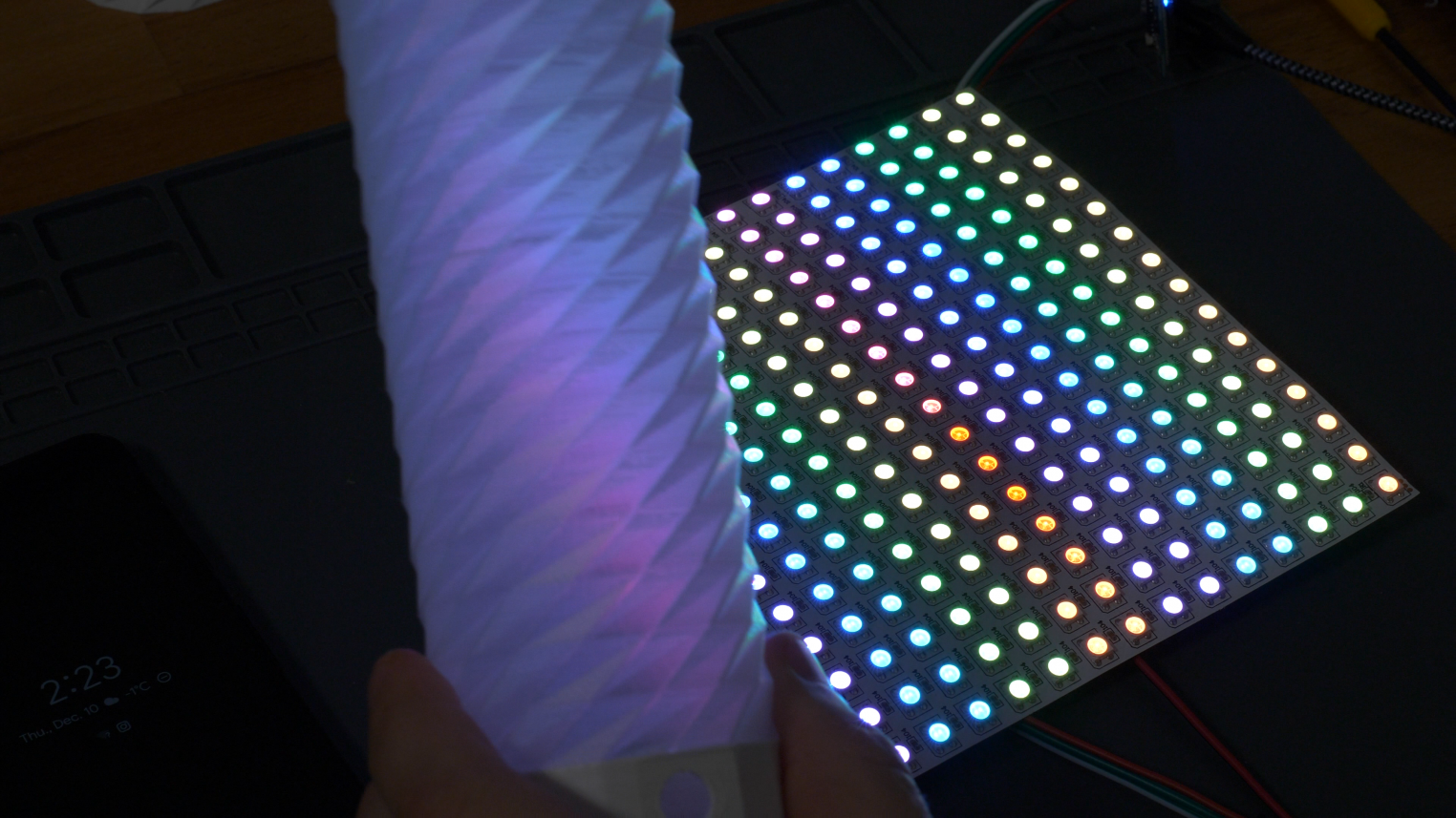
Once that is done The micro controller can be disconnected from the USB and connected to the matrix and the matrix. Once the power is plugged in it should light up. Connecting to the controls again some other patterns and colors can be set.
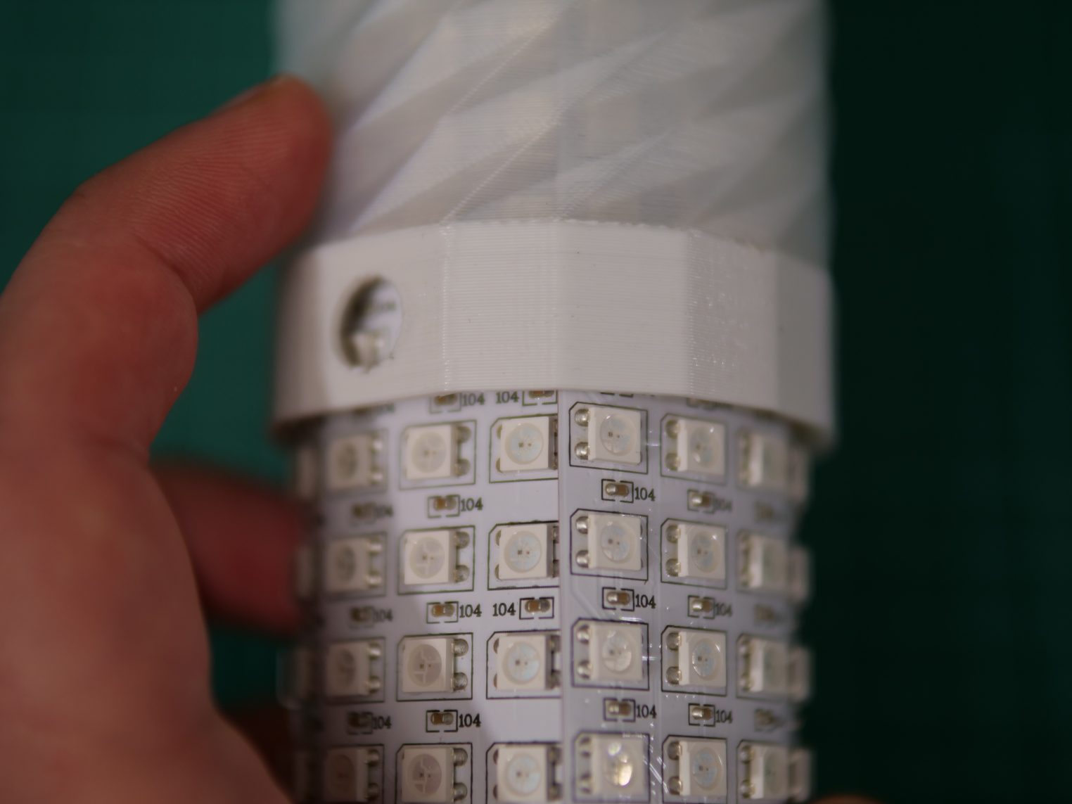
When everything is working the power should be unplugged and the matrix put inside the finished print. Rolling it such that it overlaps slightly simplifies that a bit.
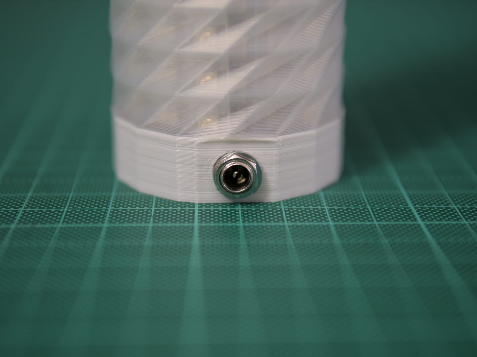
The barrel jack is mounted trough the hole and secured using the washer and nut from outside.
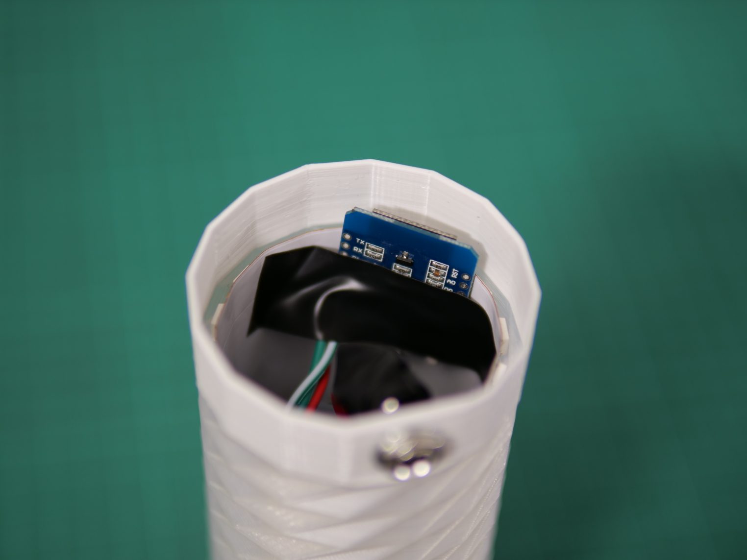
Using some tape the micro controller can be simply fixed in place. There is a PCB antenna at one end. That should not be covered by the matrix and rather point outwards like shown below. That improves the WiFi signal.
Now it’s ready to be plugged in and played around with. Have fun!